

Introduction: Raspberry Pi Pico Controlled Simple Automated Model Railroad | Model Railroad Automation


A Raspberry Pi Pico is a new addition to the family of microcontrollers. Its low cost makes it a good option for beginners. So I thought of introducing this microcontroller in model railroading. Today, let us learn how to make a basic automated oval model railroad layout using this microcontroller. So without further ado, let's get started!
Step 1: Get the Required Parts and Components


You will need:
- A Raspberry Pi Pico
- An *L298N motor driver
- A 'sensored' track.
- 4 male to male breadboard jumpers(2 for connecting track power lines to the motor driver and 2 for connecting Pico's power and GND to the motor driver)
- 6 male to female jumper wires(3 for connecting the output pins of the Pico to the motor driver and 3 for connecting the sensor to the Pico)
- A female DC jack connector(Optional, you need this if your power adapter has a barrel jack like usual, or you can also cut it off, strip the wire insulation and connect them directly to the motor driver's power terminals)
- A screwdriver
*A good feature of this motor driver is its onboard voltage regulator which can create 5-volts, not only for the motor driver but also for other external modules and microcontroller which can be powered through the +5V terminal of the motor driver module.
Step 2: Program the Pico

Program the microcontroller with the given code using the Arduino IDE. I would recommend you go through the code to get an idea of how it works and how you can tinker with it.
You can learn how to program a Raspberry Pi Pico with the Arduino IDE from here.
Attachments

Step 3: Set Up the Layout.

Click on the picture for more information. Make sure to make proper rail joints to prevent derailing. After setting up the layout, clean the rails to ensure proper electrical contact between the locomotive's wheels and the rails.
Step 4: Connect Track Power to the Motor Driver

Connect the track power wires to the output terminals OUT1 and OUT2 of the motor driver.
Step 5: Connect Input and Output Power Wires to the Motor Driver
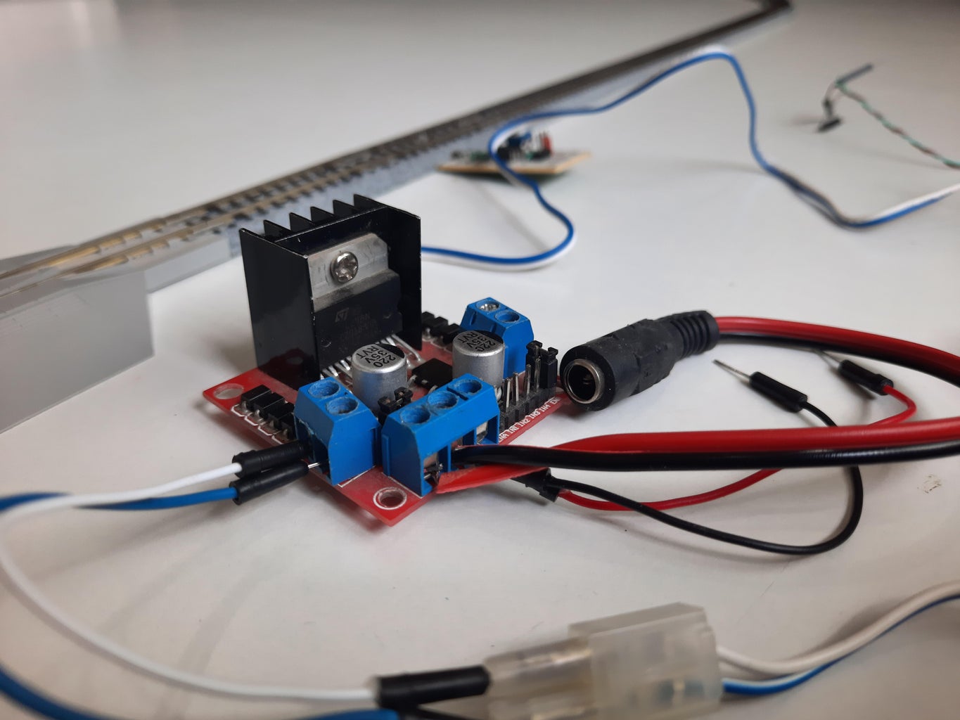

Connect the female DC jack's +ve wire to the +12-volt(Left) terminal, connect a male jumper and the -ve wire of the DC jack to the GND(Center) terminal. Connect a jumper wire to the +5V(Right) terminal of the motor driver.
Now there will be two jumper wires coming from the motor driver's GND and 5V pin which will power the Pico.
Step 6: Connect the Pico to the Motor Driver


Connect the 5V wire from the motor driver to the pin VSYS of the Pico, connect the wire from the GND of the motor driver to the GND pin of Pico. Then make the following connections between Pico and the motor driver:
- GP7 -> ENA
- GP8 -> IN1
- GP9 -> IN2
You can change the above three wiring connections by changing the pin numbers in the code.
Step 7: Connect the 'sensored' Track to the Pico

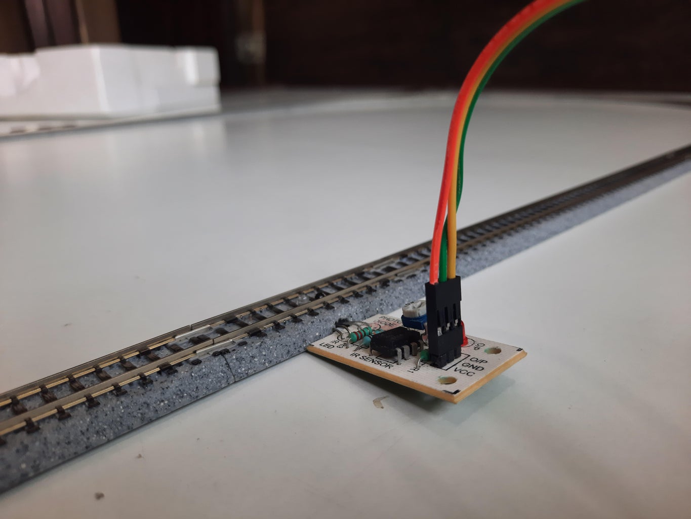
Connect the VCC pin of the sensor to the 3V3 pin(Not 3V3 EN) of the Pico, GND of the sensor with GND pin of the Pico, and the output pin of the sensor to pin GP1 of the Pico.
Step 8: Tidy Up the Wires

Although optional, keeping the track power and sensor wires tied up can prevent them from getting on the track and help prevent derailments.
Step 9: Connect the Setup to Power

Check all of the wiring connections and then connect the driver to the 12-volt adapter.
Step 10: Place the Train on the Tracks

The use of a rerailing tool is highly recommended, especially for steam locomotives.
Step 11: Power Up the Setup
- If the train starts to move in the wrong direction, reverse the polarity of the track power.
- If the train does not move at all, check the wiring and ensure both the motor driver and Pico are powered up, the LEDs on both of them should be lit.
- Make sure the LED on the sensor lights up only when the train crosses it. If the LED is lit all the time, adjust the sensitivity using the potentiometer on the sensor.
Step 12: Tinker With the Project

Now that you have got your train running around, try changing some values in the code to adjust the speed of the train, stopping time, and a lot more. You can also add some more functions, like another 'sensored' track in the layout, and adjust the code to make the train stop at two points on the layout. All the best!


